
Lockheed Aircraft civilian contractor
Lockheed had an assembly line in Edison, New Jersey where they manufactured a special type of electrical meter and various specialty parts for microwave communications. But they also had a separate machine shop as part of their “skunkworks” that designed and built prototypes of top secret classified military projects.
I was originally hired as a journeyman tool maker assigned to work in the shop that maintained the production line for the electrical meters. But following my interview with Tom Brennen, the special projects manager in the shop responsible for fabricating prototype designs for military projects, I was transferred to the prototype shop as it was then called. This was a fantastic machine shop with state of the art precision metalworking machines, Monarch precision lathes, Bridgeport milling machines, Moore precision jig borer and highly accurate surface grinders. With the proper skills and this machinery, you could make any mechanical device that could be dreamt up, and we did. I was assigned to work with a team of three senior toolmakers, Frank Herd, Steve Schupak, and Willie Kamm under the supervision of Tom (snake hips) Brennen.
Lockheed Skunkworks – The Projects
From its inception, in 1966, until its completion on September 17, 2011, the Hexagon project was a classified top secret military operation. Lockheed was the primary contractor for design and fabrication of this reconnaissance (aka spy) satellite which was the early precursor for the Hubble Space Telescope. I was fortunate to have the opportunity to work on the Hexagon project. For years people would ask me if I was in the US Armed service during the Vietnam War and I would tell them no, but I was a civilian contractor for special projects for the US Air Force and Navy. I was legally bound not to discuss the details of what I had done so when asked I would quickly change the subject. I’m sure many didn’t really believe me and probably thought I was a conscientious objector or a rejected on medical grounds or something. Finally, in September of 2011 no longer did I have to change the subject and I could now divulge what I actually did. But many I’m sure still didn’t believe me. Most people outside of those that actually worked on the program don’t even know it existed.
However, it was great experience. I had the opportunity to work with some brilliant engineers and scientists from Lockheed as well as the Jet Propulsion Laboratories in Pasadena, CA and Caltech all of whom had major roles in the development and construction of the satellites. I was an evening student at Newark College of Engineering and that extraordinary group of people became my role models.
KH-9 Hexagon
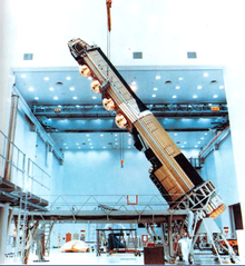
KH-9 Hexagon during assembly by Lockheed
Mariner Projects
Another similar, but scientific rather than military project, I had the opportunity to work on was the Mariner satellites. Mariner 6 and 7 comprised a dual-spacecraft mission to Mars, the sixth and seventh missions in the Mariner series of spacecraft used for planetary exploration in the flyby mode. The primary objective of these missions was to study the surface and atmosphere of Mars during close flybys and establish the basis for future investigations, particularly those relevant to the search for extraterrestrial life. As well as to demonstrate and develop technologies required for future Mars missions and other long-duration missions far from the Sun.
Mariner 6 had the objective of providing experience and data which would be useful in programming the Mariner 7 encounter which was launched five days later. Each spacecraft carried a wide- and narrow-angle television camera, an infrared spectroscope, an infrared radiometer, and an ultraviolet spectroscope. The spacecraft were oriented entirely for planetary data acquisition.
This is a schematic of a later version of the Mariner showing the major components and features.
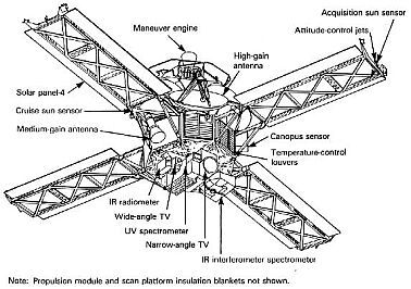
The Mariner 6 and 7 spacecrafts were identical. They consisted of an octagonal magnesium base plate or frame, a conical superstructure mounted on top of the frame that held a parabolic antenna and four solar panels affixed to the top corners of the frame. Underneath the octagonal frame was another platform which held a variety of scientific instruments.
The spacecraft was attitude stabilized in three axes (referenced to the sun and the star, Canopus) through the use of gyros and nitrogen jets mounted on the ends of the solar panels, a Canopus tracker, and two primary and four secondary sun sensors. Propulsion was provided by a rocket motor mounted within the frame which used hydrazine as the propellant.
Power was supplied by photovoltaic cells covering the four solar panels. These panels provided electrical power and a rechargeable silver-zinc battery provided backup power. Thermal control was achieved through the use of adjustable louvers on the sides of the main compartment. Three telemetry channels were available for telecommunications. Channel A carried engineering data, channels B and C carried science data.
Communications were accomplished with high- and low-gain antennas. An analog tape recorder with a capacity of 195 million bits could store television images for subsequent transmission. Other scientific data was stored on a digital recorder. The command system, consisting of a central computer designed to actuate specific events at precise times. It was programmed with a standard mission and a conservative backup mission before launch, but could be reprogrammed in flight.
I worked on building the data recorders and the main octagonal base plate that supported all of the scientific instrumentation and recorders. My first job on Mariner 6 was to machine the magnesium base plate, the foundation for the spacecraft; a complex piece of work.
There were numerous small threaded blind holes for attaching the instruments and high precision angles with threaded holes to position the data recorders. I cut the base plate from a one-inch thick piece of magnesium stock, machined the edges and started on the numerous holes in precise locations on the plate. It was a long and tedious process and after expending approximately 200 manhours I was nearly finished and had only to locate and drill a final half inch diameter positioning hole. I finished boring the hole and double checked the location with my ruler. Something was wrong! The hole should have been located 6 inches from the center of the base plate but the ruler told me it was 7 inches. I checked the blueprint and 6 inches was correct, but the ruler said 7 inches and the ruler doesn’t lie.
I suddenly became weak in the knees. I had drilled the hole exactly one inch away from where it was supposed to be. Holy shit. I already had 200 manhours into the project and with this one mistake it was ruined.
I sat and contemplated this mistake for a considerable time. After a while, I decided rather than start over I would fix the mistake. When I was an apprentice at Heller Machine and Tool I learned how to fix a mistake like this so long as it wouldn’t introduce a structural defect in the part. And so, I went to the material storage area, found a piece of magnesium bar stock, cut off a piece and machined it on the lathe to a press fit in the ½ diameter hole. The trick to doing this correctly is to very slightly chamfer each side of the hole (top and bottom) and cut the plug a little longer than it needs to be. The next step is to very carefully peen the protruding ends of the plug very gently with a small ball peen hammer so that the peened metal spreads and folds over into the chamfer. The final step is to grind the top and bottom flush with the surface very carefully. Done properly the plug is nearly impossible to detect even under magnification. I finished the part and sent it over to the inspection department to be checked out. The inspectors never detected the plug and passed the part with “flying colors”.
About two weeks later, Tom, the foreman, came out to the shop to see me and said, “You know that base plate you made for Mariner, we sent it out to be anodized (a kind of surface plating which turns magnesium to a pale yellow) and the plater must have screwed up.” I asked how and he told me there is a dark brown spot on the surface about ½ inch in diameter. He said “the plater must have laid something on the surface that turned that spot dark brown”.
I had to own up. I told Tom the plater didn’t screw up. The brown spot must be the plug. He exclaimed what plug? I told him that I screwed up and plugged the hole with a piece of magnesium bar stock of a slightly different grade of magnesium that must have turned dark brown when anodized. He then exclaimed, “Inspection didn’t catch that?” I said no it passed right through. He then was silent for a long while. When he spoke up he said, “Damned impressive.” Followed by, “Well, cut off another piece of flat stock and make another base plate.” As he was leaving the shop he said, “Don’t screw this one up or we’ll both be looking for a job!” The second one was a lot easier and quicker to make than the first one and this one was perfect. It was the one that went into the satellite that flew to Mars.
What happened to the “bad” one? Well it was an outstanding looking piece and since no one but Tom and I knew that it was defective, management decided to enclose it in a glass case and exhibit it in the lobby of our building as an example of the impressive type of work we were accomplishing.
From time to time we would be visited by various politicians, dignitaries, and other assorted influence peddlers that would be given a guided tour through the Lockheed facilities including our special projects shop. Before these tours, we would retrieve the “bad” base plate from the lobby showcase and strap it on the jig borer in the shop. I would don a white lab coat and protective eye goggles, start the jig borer and essentially screw around with the “bad” base plate as the tour group gathered around behind me. They would all nod approvingly and mumble comments such as “very impressive”, “well done”, “carry on”, etc., etc. They didn’t really have a clue what they were looking at but it looked complicated and “very impressive”. Tom and I would always have a good laugh over these dog and pony shows when we retuned the “bad” base plate to its resting place in the glass case in the lobby.
We also built the data recorders that went into the satellite. There were two recorders onboard; an analog tape recorder with that could store television images for subsequent transmission and a digital recorder for other scientific data. The recorders would record at a relatively slow speed and then playback and transmit at very high speed. These were similar to conventional tape recorders used at that time in the music industry. There were two reels side by side, one for the Mylar recording tape before running through the recording head and another to take up the reel as the data was recorded. Weight was a critical consideration so every effort was made to reduce overall weight to an absolute minimum.

A problem arose early in the design of the data recorders. The original plan for each recorder specified two small electric motors, one on each shaft that supported the reels containing the Mylar recording tape. The problem was as the tape ran from the supply reel through the recording head to the take up reel, in order to maintain the tape at a constant linear speed through the recording head, the rotational speed of the shafts needed to vary. A complicated arrangement including electronic circuitry was devised to constantly adjust the rotational speed of each motor as the tape proceeded from one reel to the next. In addition to the complicated electronic circuitry, two motors exceeded the weight limitation specified for each of the recorders.
One of my shop mates, Steve Schupack, an excellent tool maker with only an eighth-grade formal education looked at this problem and within a few minutes came up with an absolutely elegant solution. He suggested eliminating the two motors and the electronic circuitry and instead use only one motor at constant rotational speed. Here is how he did it. He suggested putting a third shaft driven by a single motor outside of the two reels of tape. In addition, a belt of suitable material enveloped the two reels and the motor driven shaft. To record, the motor would drive the reels by means of the belt at constant linear speed. The diameter of the supply reel diminished as the tape ran through the recording head to the take up reel. The take up reel diameter would increase correspondingly as the tape was wound on this reel. To play back, the motor would simply be reversed. The reverse process would occur with constant rotational and constant linear speed. Wow, brilliant! Not only brilliant, but elegant. Lockheed presented Mr. Shupack with a $25 US Savings bond for the idea. And I learned a valuable lesson. Never underestimate a blue collar guy that knows how to build stuff with his hands
My career as a tool maker for the Lockheed skunkworks was a terrific educational experience and a very rewarding job. To this day I’m extremely proud of my contribution to those landmark projects and believe it was a much more productive use of my time than slogging through the jungles of Vietnam carrying a rifle and shooting at “Charlie” in the trees. God Bless the foresight of that gentleman at the local draft board for providing me with this outstanding opportunity. And incidentally there were no digital computers available at that time. The entire projects were designed with slide rules, mechanical adding machines, hand drawn blueprints and specifications written with typewriters.
Good bye, good luck and have a nice day!
